One of the unique features of the ANTz visualization tool is the support of animations using what we call 'channels'. In addition to the ANTz node and tag files, ANTz supports additional files for creating animations. These are the "channels" file and the "channel map" file. Here are some examples of what ANTz can do:
Download the HPWREN weather data animation in Windows format.
Download the synesthetics animation for Windows.
Download the bike rental activity animation for Windows.
Download the physiometric demo for Windows.
Planet Terrena and the Four Moons:
Animating Moons Around Planets With Channels
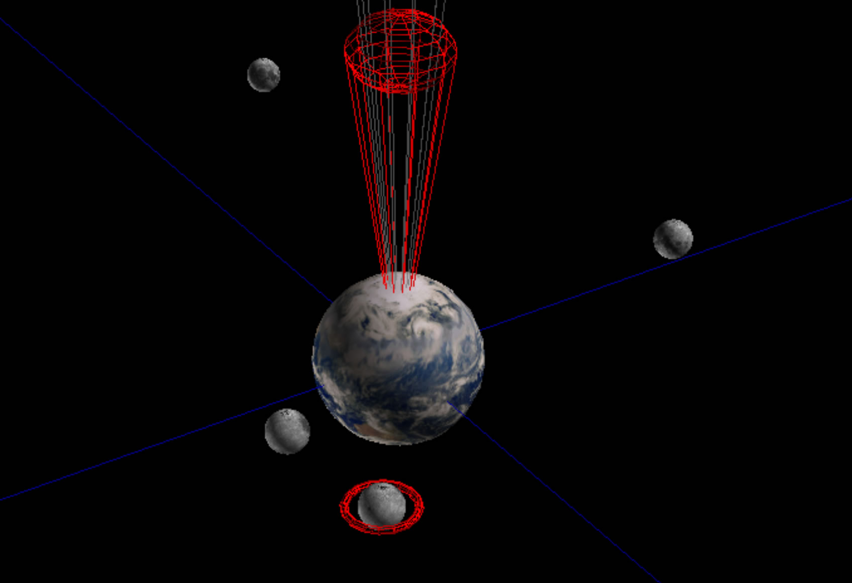
In this lesson, I provide a simple example of how to animate one object so it orbits another object. Hyperglyphs can sometimes be useful even when they are not necessarily abstract structures. This examples was inspired by my daughter's request for an app which allows her to try out different orbital periods for a set of 4 moons around a planet she calls "Terrena" for a science fiction fantasy story she is writing.
Download the final animation for Windows.
Download the final animation for Mac OS X.
First, let's explore the file formats for the channel and channel map files. We will make some simple changes and observe their effects.
With whatever time remains, we will try to create some simple animations manually using spreadsheet software.
ANTz Channels are designed to support dynamic animation of several object parameters including scale, translation, rotation, color, geometry, and more.
There are two CSV format files which contain all of the relevant data for animatons:
1) Channels file, antz0001ch.csv
2) Channel map file, antz0001chmap.csv
The Channels file contains the actual data to be used to modify the particular object's animation. Below is a simple example of a Channels file format:
| cyclecout | ch1 | ch2 | ch3 | ch4 | ch5 |
| 0 | 180 | 180 | 180 | 180 | 180 |
| 1 | 179 | 179.5 | 179.6667 | 179.75 | 179.8 |
| 2 | 178 | 179 | 179.3333 | 179.5 | 179.6 |
| 3 | 177 | 178.5 | 179 | 179.25 | 179.4 |
| 4 | 176 | 178 | 178.6667 | 179 | 179.2 |
| 5 | 175 | 177.5 | 178.3333 | 178.75 | 179 |
| 6 | 174 | 177 | 178 | 178.5 | 178.8 |
| 7 | 173 | 176.5 | 177.6667 | 178.25 | 178.6 |
| 8 | 172 | 176 | 177.3333 | 178 | 178.4 |
The 'cycleCount' column represents time 'tic' values which determine the order of animation playback. This is not an actual time increment. Animation playback occurs as fast as one's computer processors can render it. There are future plans to provide an option to specify a time increment. The columns labelled 'ch1' through 'ch5' contain the actual channel data. This can represent position coordinates, size values, or rotational degrees, etc.
The Channel map file contains the details needed to identify which data from the Channels file maps to which parameter of the object. Below is a simple example of a Channel map file:
| id | channel_id | track_id | attribute | track_table_id | ch_map_table_id | record_id |
| 0 | 1 | 1 | translate_x | 0 | 0 | 1 |
| 1 | 2 | 2 | translate_x | 0 | 0 | 1 |
| 2 | 3 | 3 | translate_x | 0 | 0 | 1 |
| 3 | 4 | 4 | translate_x | 0 | 0 | 1 |
| 4 | 5 | 5 | translate_x | 0 | 0 | 1 |
| 5 | 6 | 6 | translate_x | 0 | 0 | 1 |
| 6 | 7 | 7 | translate_x | 0 | 0 | 1 |
| 7 | 8 | 8 | translate_x | 0 | 0 | 1 |
| 8 | 9 | 9 | translate_x | 0 | 0 | 1 |
| 9 | 10 | 10 | translate_x | 0 | 0 | 1 |
The 'id' column identifies the current row. The 'channel_id" column contains the number which corresponds to the value of 'ch_input_id' for the object in the Node file. The 'track_id' column specifies which column in the Channels file is to be used for this specific object parameter. That parameter is specified in the 'attribute' column. The remaining 3 columns are not currently being used by ANTz.
In the above example, the first row after the header row specifies that any object in the Node file with 'ch_input_id' set to 1 will have its translate_x parameter animated by column 1 in the Channels file, likewise for values 2 through 10. If you open the Channels file in a spreadsheet application and plot a graph of the 10 channels you will see they are sinusoidal with varying wavelengths, or in this case varying peroidic orbits.
The above Channel Map file is fairly conventional. Each column in the Channel file modifies only one parameter, in this case translate_x. Channel Map files don't have to be so simple. The example below controls a variety of parameters, some with the same column in the Channel file. In this example, objects with ch_input_id = 1 in the Node file will have both their translate_x and translate_y parameters modified by column 1 in the Channels file, but their translate_z parameter will be controlled by column 2 in the Channels file.
| id | channel_id | track_id | attribute | track_table_id | ch_map_table_id | record_id |
| 0 | 1 | 1 | translate_x | 0 | 0 | 1 |
| 1 | 1 | 1 | translate_y | 0 | 0 | 1 |
| 2 | 1 | 2 | translate_z | 0 | 0 | 1 |
| 3 | 2 | 2 | translate_y | 0 | 0 | 1 |
| 4 | 3 | 3 | scale_x | 0 | 0 | 1 |
The key parameter in the Node file which determines whether an object is animated or not is the "ch_input_id". This parameter typically defaults to a value of '0' for no animation. Using integer values of 1 or greater, the Channel map file will use that value to identify which parameter is to be animated by which column of data in the Channels file.
| id | type | data | selected | parent_id | branch_level | child_id | child_index | child_count | ch_input_id |
| 1 | 0 | 1 | 0 | 0 | 0 | 0 | 0 | 0 | 0 |
| 2 | 1 | 2 | 0 | 0 | 0 | 0 | 2 | 3 | 0 |
| 3 | 1 | 3 | 0 | 2 | 1 | 0 | 0 | 0 | 0 |
| 4 | 1 | 4 | 0 | 2 | 1 | 0 | 0 | 0 | 0 |
| 5 | 1 | 5 | 0 | 2 | 1 | 0 | 0 | 0 | 0 |
| 6 | 6 | 6 | 0 | 0 | 0 | 0 | 0 | 0 | 0 |
| 35 | 5 | 35 | 0 | 0 | 0 | 0 | 1 | 4 | 0 |
| 36 | 5 | 36 | 0 | 35 | 1 | 0 | 0 | 0 | 4 |
| 37 | 5 | 37 | 0 | 35 | 1 | 0 | 0 | 0 | 3 |
| 38 | 5 | 38 | 1 | 35 | 1 | 0 | 0 | 0 | 2 |
| 39 | 5 | 39 | 0 | 35 | 1 | 0 | 0 | 0 | 1 |
So, what happens if we change translate_x to translate_y for one of the rows in the Channel Map file?